INTRODUCTION
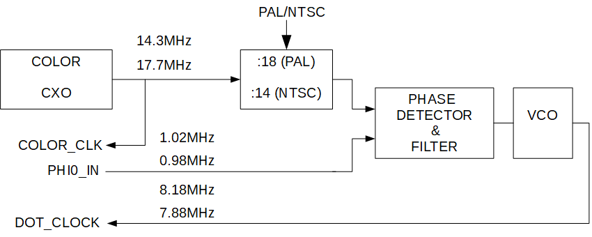
The C64 can only work properly with stable clocking. In a C64 II the MOS 8701 IC generates two major clocks and maintains the fixed frequency and phase relationship. COLOR_CLK is the main crystal oscillator clock and DOT_CLOCK is derived thereof. This blog presents a replacement circuit for the MOS 8701 IC.
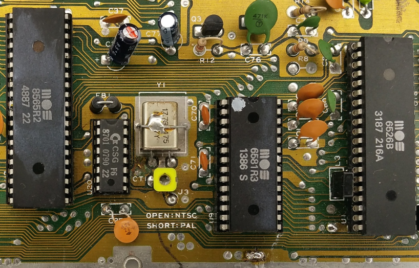
Orginal MOS 8701 (U20) and crystal Y1
Block diagram MOS 8701

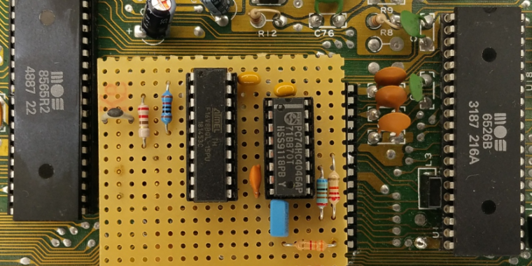
Replacement Circuit
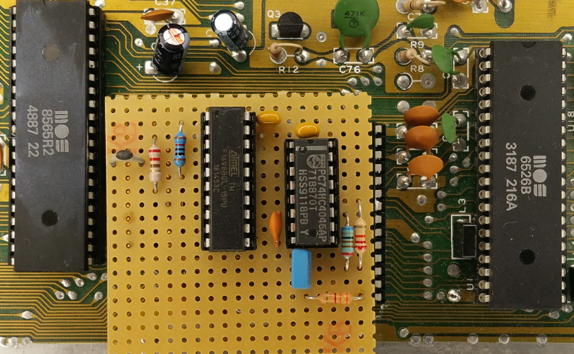
Block Diagram
FEATURES
- Utilizes crystal Y1 on PCB
- Utilizes PAL/NTSC jumper on PCB
- Simple circuit, no fancy parts
- Easy-to-build
LET’S GET STARTED

Schematic
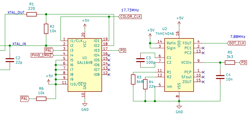
Circuit Description
In order to keep the complexity low, a PLL is used instead of a frequency doubler. All logic for the phase detector, programmable frequency divider and oscillator is implemented in U1. The VCO, provided by U2, generates DOT_CLOCK (7.88 MHz) for the VIC. A division of DOT_CLOCK by 8 (PHI0_IN=DOT_CLOCK/8) within the VIC closes the PLL.
ABEL Design
MODULE

TITLE 'C64 MOS8701 Replacement'
"Yorck Thiele, December 2020

DEVICE  'p16v8';

"inputs
clk                 pin 1;"PAL: 17.734472MHz, NTSC: 14.31818MHz
color_clk_in        pin 2;"XTAL in
ntsc_pal            pin 3;"0=PAL, 1=NTSC
phi0_in             pin 4;"VIC pin17;PAL: 0.985MHz, NTSC: 1.023MHz

"outputs
color_clk_buf       pin 19 istype 'com';
color_clk_out       pin 18 istype 'com';
phase_comp          pin 17 istype 'com'; "Phase Comparator phi0

Q0,Q1,Q2,Q3,Q4      pin 12,13,14,15,16 ISTYPE 'reg';

count            =  [Q4..Q0];

EQUATIONS

color_clk_out= !color_clk_in;
color_clk_buf= color_clk_out;

phase_comp=Q3 # !phi0_in & phase_comp; "RS flipflop (Q=S # !R & Q)

"PAL: phi0=clk/18; NTSC: phi0=clk/14
"dot_clk=phi0*8
WHEN (count==17) & (ntsc_pal==0) THEN count:=0 ELSE WHEN (count==13) & (ntsc_pal==1) THEN count:=0 ELSE count:=count+1;

count.clk=clk;

END