INTRODUCTION
This Digital Multimeter (DMM) is built from off-the-shelf components around an Arduino Nano without the use of a sophisticated front-end ASIC. This blog enables you to build a practical DMM for the everyday use on your bench. But more importantly you’ll get an understanding about the functionality of a DMM, analog to digital conversion, precision measurement, specifications, analog front-end, range switching and much more.
Looking Back
In the 1980s there were a few DIY DMMs and panelmeter kits e.g. DMM7001, DMM7002, DVM7106 & DVM7107 from ELV magazine. These used the now industry standard ICL7135, ICL7129, ICL7106, ICL7107 and the less popular TL/TLC500 Integrated Circuits. Then cheaper DMMs from Hong Kong and Korea became popular and thus DIY DMMs less attractive. Today’s modern DMM front-end ASICs are highly integrated and provide a ton of functions. Just to name a few ASICs: FS970X, HY313X, ES51997, DTM0660.
SAFETY WARNING!
NanoDMM ist intended for indoor use on mains isolated devices and appliances only. Make sure you are familiar with its capabilities and limitations. Otherwise it may result in electric shock, fire and/or serious injury. Safety rating is CAT I.
When operating the NanoDMM without covers then be aware of the fact that the measurement circuit analog common is capable of being driven up to 350 V above earth ground.
All measurement circuits are therefore potentially hazardous, including the Arduino Nano board.
Make sure the supply for the NanoDMM is current limited or fused.
Make sure to disconnect all test leads before connecting the Arduino Nano’s USB.
AMPS overload protection:
Ranges up to 250 mA are PTC fused. The withstand voltage in case of an overload is 60 V DC.
The ACS712 current sensor module has no protection at all.
NanoDMM Overview/Features:
- Firmware programming via USB/Arduino IDE
- Interface HC05 Bluetooth Wireless RF-Transceiver-Module
- 5V DC/500mA USB or wall adapter supply
- Input circuit is floating (isolated) with respect to 5V supply
- Beeper for Continuity and Logic Test
- 4.5 digits; 28000 counts
- 2.5 readings/s
- integrating ADC; 2.5 V with 300 mV overrange
- noise-free MOSFET relay front-end switching
- DC Voltage: 250 mV to 250 V
- AC Voltage: 250 mV to 250 V
- DC Current: 250 uA to 250 mA (referenced to LO input)
- DC Current isolated: 5 A/20 A/30 A with ACS712 current sensor
- Resistance: 25 Ω to 250 MΩ with fast Auto-Ranging up to 2.5 MΩ
- Continuity Test: fast response 600 samples/sec with audible tone and latching
- Logic Test: 100 samples/sec with audible tone
- Diode Test: Max. 9 V diode drop (25 V DC range with 1 mA current source output)
- Capacitance: 1000 pF to 200 mF (reading within C * 0.05 seconds; capacitance in mF)
- Capacitor ESR: 100 Ω; 10 mΩ resolution
- Inductance: 20 µH to 20 H
- Square Wave Generation: 31 Hz to 2 MHz; 5V peak; Source Impedance 120 Ω
Block Diagram

General Overview & Principles Of Operation
The input signal conditioning includes the input attenuator, current shunts and analog switches required for range switching. All analog switches are either CMOS gates or MOSFETs except one reed relay is needed for the ESR, Inductance and Waveform Generator function.
The reference for voltage and current measurements consists of a LT1019 2.5V reference. Resistance measurements use a 1V reference voltage derived from the 2.5V reference to generate a precision current through the unknown resistor. In the highest Ohm range the ratiometric method is used.
The input multiplexer (MUX) consists of analog gates of an MAX328 which feed the analog to digital converter (ADC) with the signals necessary to perform a complete meter reading. Each complete meter reading requires up to three ‘sub-readings’, each with a different signal fed to the ADC for the duration of one 200ms conversion period. One where the analog ground is fed to the converter is used to cancel out offset voltages within the front-end.
The buffer amplifier which drives the ADC is switched between gains of x1 and x10 according to the meter function and range.
The ADC is a self steering dynamic integrator with its output’s duty cycle measured by the ATmega328 micro controller. The counters and capture registers for the ADC reside within the ATmega328.
The basic remote interface is an wireless Bluetooth RS232, whereas the USB interface should only be used for programming and debugging.
Note:
When connecting the Arduino Nano via USB to the host then analog common is connected to its USB ground and protective earth as well. Thus the input circuitry is then no longer floating.
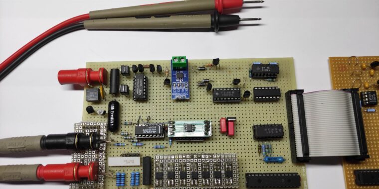
NanoDMM – Prototype


NanoDMM – Multimeter App

Select the desired function and range for the NanoDMM. Below the toolbar is a large readout for the serial output of the NanoDMM. This App can be modified and compiled with the PureBasic Demo Software. PureBasic supports Windows, Linux, OS X and Raspberry.
Create a shortcut to the App and then edit the Shortcut Properties and add a command line parameter for the App:
Target: ……………\nanoDMM.exe COM7
“COM7” is the command line parameter passed to the App to determine which ComPort to use. If your Bluetooth module uses for instance COM3 then use COM3 as command line parameter. Use this shortcut to start the App. Before starting the App make sure the Bluetooth connection with the HC05 Bluetooth module on your NanoDMM is already established. This is indicated by a slowly blinking LED on the HC05 module.
Documentation
The schematic, Arduino Nano sketch and PureBasic source code is provided in the Download Section below.
Check for more Blogs that describe the detailed operation of the circuit blocks outlined in the Block Diagram in the coming months.