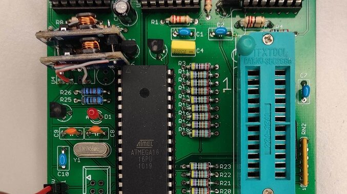


HARDWARE OVERVIEW
UART interface, 2x DCDC, ATmega16 Microcontroller, 2x PWM DAC, regulator LM723, OpAmp LM324, inverter CD4069
Supported devices
Lattice, National, ST:
GAL16V8, GAL18V10, GAL20V8, GAL20XV10, GAL20RA10, GAL22V10, GAL6001 (GAL39V18), GAL6002
GAL26V12 & GAL26CV12 by using a simple 28-pin to 24-pin adapter
Atmel:
ATF16V8, ATF20V8, ATF22V10
FEATURES
- No parallel port and driver trouble
- Power over USB
- Programms all major GAL types and ATF equivalents
- Simple circuit using off-the-shelf components
- DAC controlled VCC and VDD
- Over current protection
UART interface
Decide on one of these UART interface types for your GALmate:
USB to TTL adapter/bridge (Benefits: USB-powered, no Transceiver IC needed)
Make sure that the USB to TTL adapter supports BREAK signaling!
or
legacy RS232 (USB charger and RS232 Transceiver IC needed)
Supply
GALmate supply rating: 5V DC ±10%, 0.5A max.
Power your GALmate with an USB charger/AC adapter or over USB. The main 5V DC rail powers two DCDC converters, which provide 9V and 15V. By stacking the (isolating) 15V DCDC output on top of the 9V a 24V supply is obtained for VDD. Unlike boost-converters, DCDCs reduce complexity and avoid any boost inherent inductor hassle.
SX1308 Boost Converter
DCDC costs can be reduced by using two SX1308 (non-isolating) Boost Converters.

SX1308 setup for 8.7V unregulated VCC supply:
replace 10k potentiometer by 2k7 resistor
SX1308 setup for 21V unregulated VDD supply:
replace 10k potentiometer by 6k8 resistor
The 10k potentiometer corresponds to R1 (see schematic above) with R2=200 Ohm and VFB=0.6V.
Minor change for SX1308:
The -VOUT pin of U4 must be connected to GND!
See schematic below.

Microcontroller
An Atmel ATmega16 handles UART communication, programming timing, PWM and Target Device interfacing. Its internal 1kB SRAM buffers one complete GAL shift register content when programming.
VDD & VCC 8-bit PWM DAC
The LM723 reference 7.2V output supplies the two PWM DACs. This keeps VDD and VCC constant, unaffected by the 5V rail under normal operating conditions. A LM324 buffers both DAC outputs, amplifies and offsets one DAC voltage in order to obtain a (10V < VDD < 19V) VDD programming voltage .
As it turned out, GALs from vendor ST are very sensitive to the slew rate of VDD. A high slew rate may result in a defective GAL at the start of programming. Therefore the slew rate of VDD was greatly reduced when VDD is rising above 12V. The screen shot below shows the voltage ramp of VDD rising from 12V to 16.5V.

LM723 Voltage Regulator
A classic LM723 regulates VCC and limits ICC of the target device. ICC current limit is set to 150mA. In case of a VCC short circuit to GND, “foldback” current limiting will reduce ICC to 100mA. The external NPN pass transistor dissipates the power (9V-VCC)*ICC, and thus prevents the LM723 from excessive dissipation.
DOWNLOAD SECTION
GALmate Hardware GALmate (Eagle)GALmate schematic and PCB layout (Eagle format) provided by Roman Bórik. GALmate is featured on his Slovak blog:
https://blog.borik.net/2021/09/galmate-programator-galov.html
News
November 2021:
- Layout available (Eagle 6.5.0)
- Option: SX1308 as cheap DCDC substitution
- Added: LM723 Vref buffer 100nF capacitor for reduced VCC & VDD ripple
- Added: ATMEGA16 fuse information for programming